
The compute tray of the NVIDIA Vera Rubin NVL72 has moved to a fanless design, relying completely on liquid cooling to carry the heat away; cold plates are split into ever smaller pieces, and the number of coolant connections jumps accordingly. What changes is not just the mechanical design, but the things the production line touches every day.
Jiahon Group | Technical document | For: process, facilities, quality assurance and MRO purchasing at server contract manufacturers
1 Liquid cooling is no longer an option; the maker’s specifications have fixed it
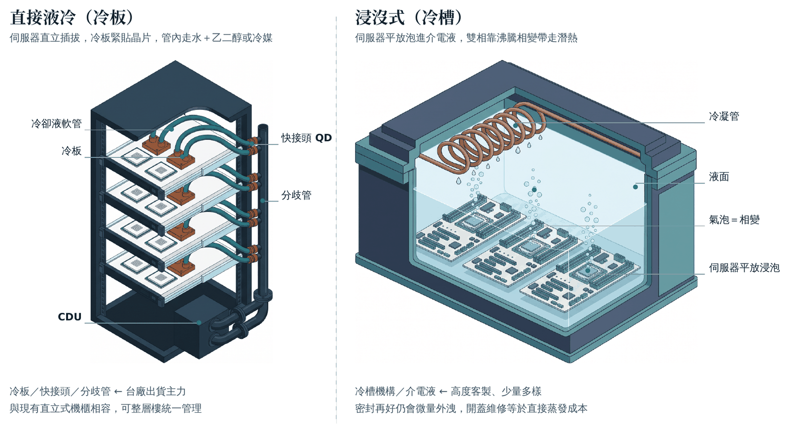
Figure 1 | Structural differences between the two liquid cooling routes. Left: direct liquid cooling — the cold plate sits tight against the chip, and the heat is carried by hoses through the manifold to the CDU. Right: immersion — the whole server is submerged in a non-conductive dielectric fluid. The left route is the current mainstream in volume production.
NVIDIA’s official technical blog describes the Vera Rubin NVL72 as following the Blackwell approach, using warm-water, single-phase direct liquid cooling (DLC) with a supply water temperature of 45°C. That sentence has two key points — single-phase, and warm water. The working fluid of this route is water plus glycol, not a fluorinated fluid.
Even more important is the coverage. With the Vera Rubin NVL72, NVIDIA officially states that the compute tray has moved to a fanless design, with the fans on the tray removed outright; the redesigned internal manifold and quick-disconnects can support a noticeably higher coolant flow than the previous generation.
The market figures line up too: a 2026 summary by Schneider Electric points out that single-phase direct liquid cooling already accounts for about 55% of the liquid cooling market and is the current mainstream approach, with a working fluid of 75% water and 25% glycol.
2 Three generations, and what differs on the production line
Table 1 | Liquid cooling configuration of three generations
| Item | GB200 NVL72 | GB300 NVL72 | Vera Rubin NVL72 |
|---|---|---|---|
| Tray fans | Yes | Yes | No |
| Cooling method | Warm-water single-phase direct liquid cooling | Warm-water single-phase direct liquid cooling | Warm-water single-phase direct liquid cooling, 45°C supply water |
| What it means for the production line | Few parts, each one large | More parts, higher fitting precision required | More connections, and no airflow to fall back on |
← The table can be scrolled left and right
The specifications in the table are compiled from NVIDIA’s official technical material. This is the general case and still depends on the individual case.
3 Variable one: cold plates go from large to small, toward microchannels
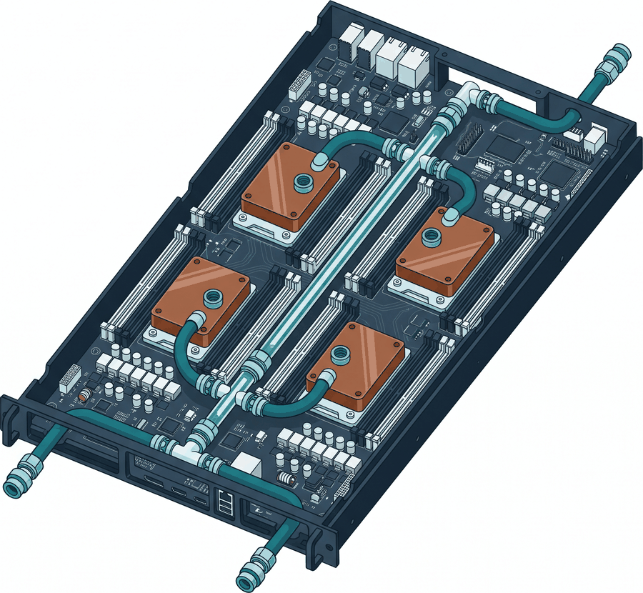
Figure 2 | Compute tray schematic. Each chip has its own cold plate, connected through quick-disconnects to the central internal manifold; there are no fans on the tray.
The trend in cold plates is a change from large integrated cold plates to small individual cold plates, one per chip. The number of parts grows, every single plate has to fit correctly, and the cold plates have to look after not just the chip core but also the VRM and the silicon interposer, while the Z-direction height (Z-height) is squeezed very tight.
Looking a generation further, the heat load of a single chip will just keep rising; for cold plates to keep up, the channels can just be made finer and the turbulence stronger.
What this means for the production line is direct: more operations, and less tolerance for error in each one. Consistency of TIM (thermal interface material) application and cleanliness of the cold plate mating surface — if any single plate is not done well, it shows up as that chip throttling.
See X23-7783D thermal grease specifications
See cleanroom wiping paper / wiping cloth specifications
See Huby-340 cleaning swabs
4 Variable two: more connections, and leakage becomes the top risk
The Vera Rubin approach gives each module its own cold plate, connected through quick-disconnects (which NVIDIA officially calls universal quick-disconnects) to the internal manifold placed in the middle of the chassis, which distributes the supply liquid and collects the return liquid. As the number of connections goes up, the chance of a leak goes up with it — and where it happens is right next to powered boards.
There is also a knock-on effect that is easy to overlook: the fans on the tray are gone. In the past, airflow could still help carry away some local heat; now everything depends on the liquid loop. As soon as the flow is insufficient, the result is hot spots and throttling, with no backup.
Plan ESD and water protection together. A common practice in liquid work areas is to add mats and water barriers, but if the grounding path is cut off for the sake of water protection, that is trading one risk for another. For ESD planning, refer to IEC 61340-5-1, and confirm that the conductive path is still continuous after changes.
See insulating rubber sheet specifications
See FR4 / G10 insulating boards
See the ESD products category
5 Variable three: the standard of cleanliness changes from “visible” to “small enough to get into the channels”
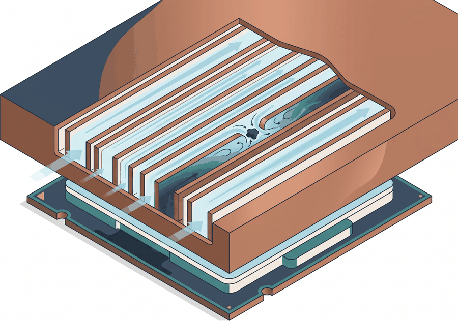
Figure 3 | Microchannel cold plate cross-section. Channel widths are often below 0.3 mm; once a particle invisible to the naked eye gets stuck, the flow in that path stops and the thermal resistance rises directly.
This is one way liquid cooling is unlike traditional cooling. In the past, cleanliness was about visible settling dust; now it is about whether something can get into channels below 0.3 mm. What blocks them cannot be seen with the naked eye, yet the symptom when it goes wrong is throttling, and the root cause is hard to trace.
There are in fact three stages to control, and if one is missing the work is wasted:
| Control stage | What to control | Common practice |
|---|---|---|
| Incoming material | Machining residue and packaging dust on the cold plates, fittings and quick-disconnects themselves | Incoming cleaning, packaging rules, particle count sampling |
| Assembly environment | Settling dust in the assembly and test areas, particles brought in by people | Cleanroom consumables, wiping materials, graded work areas |
| The coolant itself | Particles accumulated during circulation and material shed from the piping | Filter cartridge and screen configuration, replacement interval management |
← The table can be scrolled left and right
At this stage, cleaning fixtures and cold plates is no longer something “a quick wipe” can solve; it needs equipment, and a process window that can be validated repeatedly. This is the general case; the actual specifications still depend on the individual case.
See fixture / condenser spray rotary cleaning machine JHPBT-700S
See string-wound filter cartridges
See metal mesh series (stainless steel / oxygen-free copper / nickel)
6 Fluorocarbon coolants are being discontinued: where is the real impact on the production line?
Lately “fluorocarbon coolant” has been talked about as if it were a new technology; in fact it is an old material with a new story. What has really happened is on the supply side: on December 20, 2022, 3M announced it would exit all PFAS manufacturing; the last order date for the Novec and Fluorinert series was March 31, 2025, and supply ran until December 31, 2025.
For data centers, this affects the two-phase immersion route, which has therefore stopped growing; mainstream single-phase direct liquid cooling has always used water plus glycol and is not affected.
But for the production line, the impact is something else entirely. If the line’s cleaning, testing, drying or leak testing processes were already using Novec or Fluorinert, that is a real supply cut — this is where the topic really concerns you, and the deadline has already arrived.
On the regulatory side it is less urgent. The EU ECHA PFAS restriction proposal was submitted by five countries — Denmark, Germany, the Netherlands, Norway and Sweden — on January 13, 2023, and an updated version was published in August 2025; according to the European Commission’s explanation of June 2026, ECHA expects to complete the scientific evaluation by the end of 2026, after which the Commission will propose the restriction; critical industrial uses that have no substitute yet may be allowed to continue under strict conditions. It will not be banned tomorrow, but it is time to start taking stock.
See inline PCBA water-based cleaning machine JHPBT-350
JHPT Jiahon Precision Technology: cleaning and inspection process planning
7 Summary: the extra operations on a liquid-cooling line, and matching items
| New or changed operation | Main risk | Matching items |
|---|---|---|
| Cold plate fitting and TIM application | Uneven application or a contaminated mating surface raises local thermal resistance and throttles the chip | Thermal grease, cleanroom wiping cloths, cleaning swabs |
| Assembly and removal of quick-disconnects | Scratched sealing surfaces, residual foreign matter, inconsistent tightening torque causing seepage | Dedicated tools, cleanroom wiping materials, workbench protection |
| Protection of liquid work areas | Leaks spreading to powered areas; grounding paths broken for the sake of water protection | Insulating rubber sheets, FR4 / G10 insulating boards, ESD totes and racks |
| Cleaning of incoming material and fixtures | Machining residue and packaging dust getting into 0.3 mm-class channels | Spray rotary cleaning machines, water-based cleaning machines, cleaning chemicals |
| Maintaining coolant cleanliness | Particles accumulated during circulation block channels; the symptom is throttling, and the root cause is hard to trace | Filter cartridges, metal filter screens, particle count testing |
| Handling and storage of heavy racks | Weight and power density per rack rise, changing the load conditions for handling and temporary storage | Heavy-duty pallets and load-bearing bases, ESD racks |
← The table can be scrolled left and right
The table above is a general summary; the items actually introduced still have to be evaluated case by case according to plant conditions and customer specifications.
Want to take stock of which items your liquid-cooling line is missing?
Since 2010 Jiahon has served electronics plants across Taiwan, from cleaning equipment, cleanroom and ESD consumables to sourcing special materials, all through one contact. You are welcome to bring your line conditions and talk with us — contact Jiahon.
8 Also see
ESD products category — when the layout of a liquid work area changes, the grounding path must be checked again
Industrial equipment and automation parts — an overview of cleaning, inspection and process support equipment
ESD totes — carrier options for moving cold plates and modules around the plant
Technical documents — other Jiahon technical documents and selection guides
References
NVIDIA official technical blog, “Inside the NVIDIA Vera Rubin Platform: Six New Chips, One AI Supercomputer”, January 2026 (warm-water single-phase direct liquid cooling, 45°C supply water, fanless compute tray, universal quick-disconnects)
3M official announcement, “3M to Exit PFAS Manufacturing by the End of 2025”, December 20, 2022; the last order date and end-of-supply date for Novec / Fluorinert are from distribution channel announcements
ECHA, “ECHA publishes updated PFAS restriction proposal”, August 20, 2025
Schneider Electric data center blog, May 2026 (market share of single-phase direct liquid cooling and composition of the working fluid)
Further reading: Global Views Monthly (Taiwan), an article analyzing why NVIDIA’s Jensen Huang talks up cooling technology yet does not use fluorocarbon coolants (in Chinese)
This article is technical reference material compiled by Jiahon Group; the data are as announced by each primary source, and process specifications and introduction conditions have to be evaluated case by case. The schematic figures in the text were made by Jiahon.
Standards referenced
For the standards cited in this article, please follow the current revision from each publishing body.
- IEC 61340-5-1:2024 “Electrostatics – Part 5-1” Ed. 3.0
Publisher: International Electrotechnical Commission (IEC)